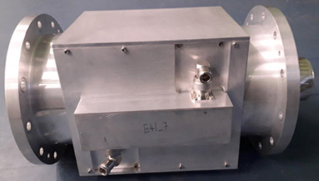

Directional Coupler is an indispensable measurement tool that provides a convenient and accurate means of sampling of RF energy in high power RF systems. Unlike other method of power sampling, Directional coupler also provides important capability of separating travelling waves in forward and reverse direction, thus enabling measurement of power levels in both directions to be precise. Especially when high power levels are involved, a Directional coupler should provide a low power signal, without any adjustment parts, that should be in the measurement range of RF sensor. For High power RF systems, RF power monitoring at multiple interfaces is a must requirement, especially with High Q RF resonators, for RF system commissioning, troubleshooting and continuous health monitoring. This is achieved with the help of high-power Directional Coupler, mostly procured from outside the country.
Forward and reflected RF measurement of High-power systems.
Directional Coupler is an indispensable measurement tool that provides a convenient and accurate means of sampling of RF energy in high power RF systems. Unlike other method of power sampling, Directional coupler also provides important capability of separating travelling waves in forward and reverse direction, thus enabling measurement of power levels in both directions to be precise. Especially when high power levels are involved, a Directional coupler should provide a low power signal, without any adjustment parts, that should be in the measurement range of RF sensor. For High power RF systems, RF power monitoring at multiple interfaces is a must requirement, especially with High Q RF resonators, for RF system commissioning, troubleshooting and continuous health monitoring.
Type and Applications
RF Performance
Directional Coupler is an indispensable measurement tool that provides a convenient and accurate means of sampling of RF energy in high power RF systems. Unlike other method of power sampling, Directional coupler also provides important capability of separating travelling waves in forward and reverse direction, thus enabling measurement of power levels in both directions to be precise. Especially when high power levels are involved, a Directional coupler should provide a low power signal, without any adjustment parts, that should be in the measurement range of RF sensor. For High power RF systems, RF power monitoring at multiple interfaces is a must requirement, especially with High Q RF resonators, for RF system commissioning, troubleshooting and continuous health monitoring. This is achieved with the help of high-power Directional Coupler, mostly procured from outside the country. There is a huge requirement of such high-power Directional couplers for ongoing as well as forth coming DAE projects.
For this coupled line Directional Coupler, rectangular cross-section coaxial transmission line has been used. Two asymmetric lines have been used as auxiliary lines on both sides of primary rectangular coaxial line. Rectangular ground planes, also incorporating continuous aperture for sampling of RF power, for both sides of primary line, have been implemented separately enabling ease of fabrication and RF shielding of electromagnetic field of primary line. Secondary line rests on this ground plane seamlessly further providing additional RF shield for primary line. Coaxial transitions, from EIA 6 1/8 inch flanged cylindrical coaxial line to this rectangular coaxial line, are also designed on both sides of primary rectangular coaxial line to for its seamless integration in standard high power RF systems.
Type and Applications
| Sr. No. | Specification | Value |
|---|---|---|
| 1 | Device Type | 60 kW CW Dual Directional coupler |
| 2 | Coupler | Rigid coaxial main line and stripline as secondary line |
| 3 | Function | Thru-line forward and Reflected RF power measurement |
| 4 | Application | Specially suited for monitoring of Dynamic VSWR RF termination in high power RF system |
RF Performance
| Sr. No. | Specification | Value |
|---|---|---|
| 1 | Frequency Range | 300 MHz to 700 MHz |
| 2 | Average Power rating | 60 kW max. |
| 3 | Thruline VSWR | ≤ 1.2 |
| 4 | Insertion Loss | ≤ 0.1 dB |
| 5 | Probes | 2 |
| 6 | Measurement Range | 1 W to 60 kW CW and 1 W to 200 kW Pulsed (25% duty cycle) |
| 7 | Typical measurement Accuracy | ±0.1 dB maximum in full range |
| 8 | Coupling | 45 dB to 55 dB |
| 9 | Typical Directivity | 20 dB min |
| 10 | Interface Connections | EIA 6 1/8 inch Female |
| 11 | Interface direction | straight |
| Sr. No. | Specification | Value |
|---|---|---|
| 1 | Size with RF connectors | 320 mm x 210 mm X 210 mm (length X width X height) |
| 2 | Gross Weight | ≤ 10 Kg |
TYPICAL END USERS
It is a thru-line bidirectional coupler thus it can be used for measuring RF power while system is working (without terminating) and monitoring line or load condition in various RF systems used for strategic applications. For example, application in solid-state high-power amplifier systems can be quoted, where a huge requirement exists for accurate and reliable measurement of forward as well as reflected powers of the amplifier modules. It finds uses for cellular base stations, military radar communications, global positioning systems etc.
List of important users of directional sensor are as follows
MANPOWER
