70 kJ, 25 kV ELECTROMAGNETIC MANUFACTURING
EQUIPMENT (EME)
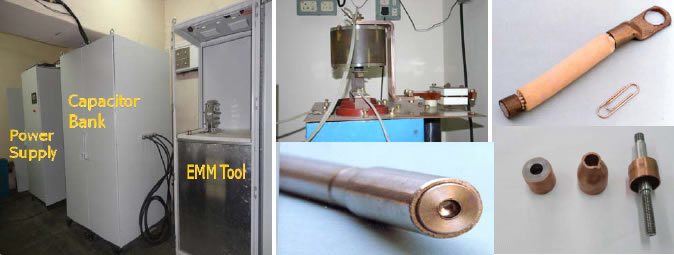
APPLICATION
- Electromagnetic forming/welding of metal sheets.
- Tubular expansion, compression and welding of similar and dissimilar metals such as aluminum plugs to aluminum rod collapsed joints, Copper lug swaged on to the aluminum multi-core cable and aluminum plug collapsed on to SS-rod.
- Aluminum was found to be the easiest to weld and it was used as driver for achieving welds in other metal combinations.
- Electromagnetic Welding is suitable for 1mm thick flat sheets of various metals such as Al-Al, Al-SS, Al-Cu, and Al-Al (alloy).
- The EM welding technique has great potential in automobile, electric, defense, aeronautical and other industries.
ADVANTAGES
The main advantages of EM Forming/Welding over conventional techniques are as follows :
- The electromagnetic pulse can be controlled to high degree of accuracy and hence the forming is highly repeatable.
- The operation of the equipment is simple which consists of charging and discharging of capacitors.
- The process does not require lubrication and leaves no tool marks.
- The joints made are stronger than the parent material unlike in all the other processes.
- Hardening takes place due to high strain rate forming, which is favorable.
- During the process of forming, the material is impact loaded into plastic region, resulting into permanent deformation.
- Field shapers can be used along with the machine and forming coil.
- Jobs of different geometry and material can be formed by changing the energy, coil and/or the field shaper. This can bring down the tooling cost considerably.
- The E.M.F. process being a non contact method, the preparatory procedures such as lubrication, cleaning are not required.
- The automation becomes easy because of elimination of manual procedures.
- It is a green process (no smoke).
WORKING PRINCIPLE
These techniques are based on Lorentz force to achieve the required goal. The force is generated when a high voltage charged capacitor bank discharges through a forming/displacement coil placed in the proximity of work piece. The force developed is on account of interaction of induced current in the work piece with the magnetic field produced by the coil. In these techniques, forming and welding are achieved without physical contact between tool and job piece.
SPECIFICATIONS
| : | 70kJ, 25kV | ||
| : | 4 Modules. Each Module consists of 4 Nos. of 14μF, 25kV, Energy Storage Capacitor |
||
| : | 400kA (maximum permissible) | ||
| : | Charging Time: 45 seconds | ||
| : | Minimum one Discharge in every five minutes | ||
: |
Input : 415V, 3 phase, 15 Amp, 50 Hz Output : 0 to 25kVDC, 200 mA |
INFRASTRUCTURE
Electrical Requirements :
- Lighting : standard illumination will be provided for the entire area
- Power (Convenience ) : Combined 5/15 A, 1 Phase, 230V, 50 Hz
- Equipment Power
- Capacitor charging power supply : 3 Phase, 415V,16 A
- PLC control system : 230V, 50Hz, 5A, 1 phase
- Separate earthing is required for energy storage capacitor banks and PLC control system. Earth resistance should be less than 1 Ohms and should follow IS 3043-1987, Indian standard code of practice for earthing.
- 400 square feet space is required for assembly, testing & installation of the EME
- Most of the components are available within the country and some components need to be imported through local agents.
MANPOWER
- An electrical engineer, a mechanical engineer & 2 trained technicians will be required for the development of this instrument.