LOW BACKGROUND GAS FLOW BETA COUNTER
INTRODUCTION
Counting of samples having very low specific beta activity becomes difficult with conventional G.M counters having high background and low efficiency. A gas flow type beta counting system developed has twin advantage of low background and high efficiency when compared with a G.M counter. This system uses a gas flow type main counter and another gas flow type guard counter both operating in the GM region. System works on the principle of anticoincidence. The counting medium is argon gas and the isopropyl alcohol vapour is used as quenching agent. A parallel gas flow arrangement is provided to make provision for counting operation of the system. The counter assembly is kept in a 3” lead shield to reduce overall background.
DETAILS OF THE SYSTEM
Perspex is used to fabricate main counter because of its low natural radioactive contamination. An aluminized mylar film of ~0.8 mg/sq.cm. is acting as window cum cathode. Window area of the counter is 16sq.cm. A tungsten wire of diameter 50micron stretched from one end of the sensitive volume of the counter to the other acts as anode. Inlet and outlet tubes are fixed at the opposite end of the counter for the gas flow. A drawer assembly has been provided to change the sample quickly without disturbing the gas flow or the high voltage supply. The material used for fabricating the guard counter is perspex or aluminium. This is large area (400 sq.cm) gas flow counter used to reduce the background. Aluminium plates are used as cathode and tungsten wire of 50micron dia are used as anode in 8 segments. The detail of the counters and the counter arrangement when in operation is shown in fig.1.
A special gas flow arrangement is provided for the smooth and continuous operation of the system. The gas flow to counter comes from two parts. One is pure argon gas (flow rate 60 cc/min) and the other one is argon gas (flow rate 20cc/min) collecting isopropyl alcohol vapour from the flask. These two lines are mixed and then passed through the counters. The gas flow of both lines can be controlled using a fine needle valve and a flow meter.
Gas Flow Counter
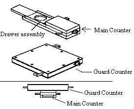
Fig. 1
PRINCIPLE
The counting system uses the principle of anticoincidence. When pulse is recorded simultaneously from the main and guard counter we will treat the main counter pulse as coincidence background pulse and hence reject it. When a pulse is recorded only in the main counter it is treated as anticoincidence pulse, which is from the sample only. Entire counter assembly, which is kept in a 3” lead shield, gives a background of less than 1 cpm when used in anticoincidence mode.
| SYSTEM CHARACTERISTICS | ||
|
|
Main Counter |
|
Plateau Threshold voltage |
~ 1100 V |
|
| Plateau length | 100 to 150 V | |
| Plateau slope | 5% for 100 V | |
| Operating Voltage | Plateau threshold voltage + 50 V | |
| Background (Inside the shield) | 8 –12 cpm | |
|
|
Guard Counter |
|
Plateau Threshold voltage |
~ 1300 V |
|
| Plateau length | 100 to 150 V | |
| Plateau slope | 8% for 100 V | |
| Operating Voltage | Plateau threshold voltage + 50 V | |
| Background (Inside the shield) | 200 to 400 cpm | |
|
|
System Performance in Anticoincidence Mode |
|
Background |
1 to 1.5 cpm |
|
| Efficiency (for 1.3MeV betas) | 40% | |
| Efficiency (for 0.15MeV betas) | 13% | |
INFRASTRUCTURE REQUIREMENT
-
Fabrication of the counter : Perspex
-
Anode wire: 50 micron tungsten wire
-
Window cum cathode: Aluminised mylar of ~0.8mg/cm2 and aluminium plate
-
Gas inlet/outlet tubes: Brass
-
Electrical connectors: MHV
-
Counting Medium: A mixture of argon gas and isopropyl alcohol vapor
-
Testing of the counters for Plateau and background (Any normal GM counting setup can be used for this purpose)
-
Manpower requirement: One Electronics Engineer and one technician having knowledge of machining